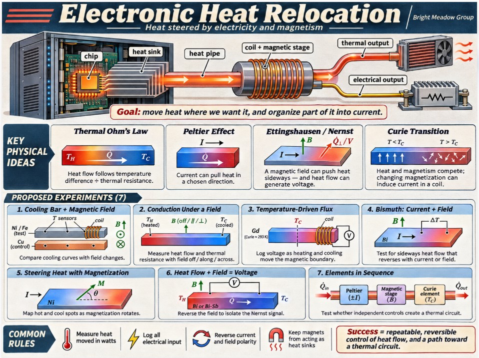
Electronic Heat Relocation — A Bright Meadow Group Research Proposal
Observe
Where this would work
Picture a server hall with no chilled air. Each processor sheds its heat into a shared heat sink. A small solid-state device at the chip end pulls heat into the sink fast enough to hold the chip at its best operating temperature. The sink runs through the cabinet wall as a heat pipe, and alongside it sits a magnetic strip wound with a coil, organizing part of the passing heat into electrical current. Outside the cabinet, a second stage pulls the far end colder so heat keeps sliding down the path. Whatever stays thermal leaves through the end of the pipe. Whatever has been organized into current leaves on a wire and gets shed through an outdoor resistor bank or into the ground below the frost line. The room only needs air handling for people and stray losses.
Every piece of that picture exists in some form today, except one. The arrangement that lets electricity and magnetism grab heat and steer it has never been put together as a working tool. That arrangement is the subject of this proposal.
Heat follows Ohm’s law, with different passengers
Electrical current through a wire follows Ohm’s law: current equals voltage difference divided by resistance. Heat through a solid follows the same form: heat flow, in watts, equals temperature difference divided by thermal resistance. A longer path adds resistance. A thicker path or a better material lowers it. Joints in series add up like resistors on one wire.
The difference sits in what does the carrying. Electrical current is charge in motion, and charge is conserved. Heat is energy in motion, and it rides on several carriers at once: free electrons drifting through the metal, and vibrations passing through the atomic lattice like a ripple through a crowd. Because electrons carry both charge and heat, pushing charge drags heat along with it. That shared passenger is the hinge between the two kinds of energy.
Current drags heat
In a thermoelectric material, heat moved by an electrical current shows up as its own term:
Heat moved = (Peltier coefficient × current) − (heat leaking back by conduction)
with resistive heating, current squared times resistance, added on top. The first term is directed. Reverse the current and it reverses. The resistive heating does not reverse, because squaring the current erases its sign. That difference gives experimenters a clean way to tell the useful effect apart from plain warming.
Magnetism turns the flow sideways
Put a magnetic field across a conductor carrying current, and the moving carriers get pushed to one side. The heat they carry gets pushed with them. One edge of the conductor cools and the opposite edge warms. This is the Ettingshausen effect, found in bismuth in 1886. Run it backward, with heat flowing through the conductor across a field, and a voltage appears at right angles to both. That is the Nernst effect, found in the same experiments.
The magnetization inside a material also shapes transport. In 2018, researchers showed that a single slab of nickel could heat in some spots and cool in others depending on the angle between the current and the nickel’s own magnetization, with no junction between two materials. Earlier work on nickel nanowires showed that thermal resistance shifts with magnetization direction.
Heat fights magnetism
Magnetic order and heat compete inside a material. As temperature rises, heat scrambles the aligned magnetic domains, and past a switching point, the Curie temperature, the material loses its magnetism. As it cools, magnetism reasserts itself. A changing magnetization means changing flux, and changing flux through a coil means current. Along a bar that runs from hot to cool, the contest plays out as a spectrum: heat holds the hot end, magnetism holds the cool end, and the boundary between them moves as the bar warms and cools.
The math already exists
Lars Onsager laid out in 1931 how coupled flows mirror each other, and Herbert Callen applied those relations to thermoelectric, thermomagnetic, and galvanomagnetic effects in 1948. The equations show heat, charge, and magnetism as linked flows with cross terms tying each to the others. The framework predicted the effects above, and experiments have confirmed them one at a time.
What’s been shown:
- A bismuth Nernst-Ettingshausen cooler reached a 101 K temperature drop with the hot side at 302 K, using an 11-tesla field and 60 amps of current.
- In 2024, a Weizmann Institute group imaged Ettingshausen cooling in microscopic flakes of tungsten ditelluride at 4 K.
- Also in 2024, researchers reported a record room-temperature anomalous Ettingshausen effect in micron-sized on-chip coolers made from Co₂MnGa, a material that carries its own magnetization.
- In 2025, a NIMS group in Japan observed a transverse Thomson effect in a bismuth-antimony alloy, with current, heat flow, and field applied at right angles to each other. Flipping the field direction switched the material between heating and cooling.
Each result needed some combination of strong fields, extreme cold, or microscopic scale. Commercial Peltier coolers, the best-developed member of the family, run at a small fraction of the efficiency the physics allows. The gap between what the equations permit and what devices deliver is wide, and it points at arrangement: which material, which geometry, which field orientation, which timing, in which sequence.
Design
The target is a thermal circuit: a path where heat flow can be switched, steered, and pushed by electrical and magnetic controls, the way current is handled in an electronic circuit.
Each element in the path combines a heat-carrying material, a controlled current, and a controlled magnetic field. Some elements drag heat with current. Some turn it sideways with a field. Some change their own thermal resistance as their magnetization changes. Some convert the passing heat into current on a coil. Placed in sequence with individual controls, they act like the parts of an electronic circuit, with resistors, switches, and pumps for heat. The long-range goal is a thermal transistor: a device where a small electrical signal controls the direction and rate of a larger heat flow.
The same arrangement works in both directions. Current can move heat, and heat can make current. Both directions belong in the research, since they are two faces of one coupled transport problem.
The path to that circuit starts with simple bench experiments that isolate each behavior.
Intervene
The program runs as a series of small experiments. Each changes one variable against a measured baseline. Common rules for the series:
- Measure heat moved in watts, using calorimetry or coolant flow × heat capacity × temperature rise. Temperature readings alone can mislead.
- Measure every electrical input, and compare heat moved against power spent.
- Reverse current and field polarity wherever possible. A signal that flips sign with polarity comes from coupled transport. A signal that stays the same comes from resistive heating or stray effects.
- Repeat each run several times without moving supports, sensors, magnets, or airflow.
- Keep magnets from touching the sample, so they don’t act as heat sinks.
Experiment 1: Magnetic field on a cooling bar.
A nickel or iron bar, with an identical copper bar as a nonmagnetic control. Three temperature sensors along each bar. An insulated pickup coil wound around the middle, logged separately from the temperatures. Heat each bar to a fixed starting temperature, such as 80°C, and record its cooling curve under five conditions:
- A. No field (baseline)
- B. Constant field along the bar
- C. Constant field across the bar
- D. Field applied and removed during cooling
- E. Field polarity reversed
Switching a field on or off induces a coil voltage by itself through Faraday’s law, so the switching spike gets logged and separated from any voltage that appears while the field holds steady.
Experiment 2: Conduction under a field.
Same bars, heated at one end with the other end held at a controlled temperature, so heat flows through the bar instead of escaping into the air. Measure heat flow and temperature drop along the bar with the field off, along the bar, and across it. This isolates how magnetization changes thermal resistance.
Experiment 3: Temperature-driven flux.
A bar of material with a Curie point inside an easy bench range. Gadolinium switches near 20°C. Hold a steady field, heat the bar past its switching point, then let it cool back through it while logging coil voltage. Then heat one end and cool the other, and pulse the cold end to sweep the heat-magnetism boundary back and forth. This isolates current produced by heat changing magnetization, the gradient-core behavior.
Experiment 4: Current and field on bismuth.
A small bismuth specimen with current along its length, a magnetic field perpendicular to it, and calibrated sensors across its width. A stable heat source and sink at the ends. Five runs:
- A. Current off, field off (passive baseline)
- B. Current forward, field off (electrical only)
- C. Current forward, field forward (magnetic coupling)
- D. Current reversed, field forward
- E. Current forward, field reversed
The test is whether reversing current or field reverses the sideways heat flow. This isolates the Ettingshausen effect, electricity and magnetism moving heat together.
Experiment 5: Steering heat with magnetization.
A nickel slab with current running through it and its magnetization set at controlled angles to the current. Map surface temperature at each angle. This repeats the 2018 nickel result at bench scale and isolates magnetization direction as a control knob for where heat goes.
Experiment 6: Heat flow and field making voltage.
A bismuth or bismuth-antimony strip with heat flowing along it and a field across it. Measure voltage at the side contacts. Reverse the field to separate the Nernst voltage from stray thermoelectric offsets. This isolates the reverse direction: magnetism organizing heat into current.
Experiment 7: Elements in sequence.
Once the single-behavior experiments have numbers, link two or three elements along one heat path with independent current and field controls. Test whether switching one element’s controls changes heat flow through the others. This is the first step toward a thermal circuit, and from there toward the full system described at the top of this proposal.
Expected Findings
- Experiment 1 should show small but repeatable changes in the magnetic bar’s cooling curve with field orientation, and no change in the copper control. Coil voltage during steady-field cooling should be small, with clear spikes at field switching.
- Experiment 2 should show thermal resistance in nickel or iron shifting with field direction, smaller in size than the matching electrical resistance shift, consistent with the nanowire findings.
- Experiment 3 should produce measurable coil voltage as the bar crosses its switching temperature, near zero once the bar settles, and repeated pulses as the cold end gets cycled.
- Experiment 4 should show sideways heat flow that reverses when current or field reverses, standing apart from resistive heating, which stays the same under both reversals. At bench field strengths and room temperature the effect should be modest, with the run data showing how it scales with field and current.
- Experiment 5 should show heating and cooling spots on the nickel slab that move as the magnetization angle changes.
- Experiment 6 should show a side voltage that flips sign with the field and grows with heat flow.
- Experiment 7 should show whether elements in sequence can be controlled independently, and how much each element’s settings affect its neighbors. That result sets the design rules for building a thermal circuit.
The program measures success by whether each behavior can be isolated, repeated, and reversed on command, and whether the combined measurements reveal an arrangement that moves heat with electricity and magnetism more efficiently than current devices do.
Sources:
- Ettingshausen, A. von and Nernst, W., Annalen der Physik (1886)
- Onsager, L., “Reciprocal Relations in Irreversible Processes,” Physical Review 37 (1931)
- Callen, H.B., “The Application of Onsager’s Reciprocal Relations to Thermoelectric, Thermomagnetic, and Galvanomagnetic Effects,” Physical Review 73 (1948)
- Kimling, J. et al., magneto-thermal resistance in nickel nanowires, Physical Review B (2013)
- Uchida, K. et al., “Observation of anisotropic magneto-Peltier effect in nickel,” Nature 558 (2018)
- Völkl, T. et al., “Demonstration and imaging of cryogenic magneto-thermoelectric cooling in a van der Waals semimetal,” Nature Physics 20 (2024)
- “Record-high Anomalous Ettingshausen effect in a micron-sized magnetic Weyl semimetal on-chip cooler,” arXiv:2403.13598 (2024)
- Transverse Thomson effect in Bi₈₈Sb₁₂, arXiv:2501.05857 (2025), NIMS
- Review of Nernst-Ettingshausen cooling, National Science Open (2025), nso-journal.org/10.1360/nso/20250009